Design of an Antenna tilt mechanism
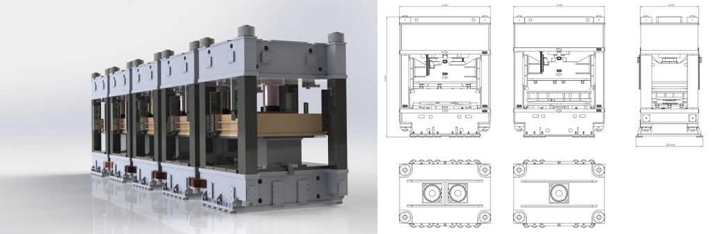
In the context of refurbishing an antenna used for tracking signals from satellites dedicated to meteorological surveys, Altamax was tasked with designing a tilting mechanism that could be integrated into the existing structure without invasive modifications. The antenna featured a manually adjustable segment, and the new device needed to maintain the original footprint.
The project specifications included:
- Rotation Speed: 12° in 70 seconds
- Operational Range: ±6° measured by the encoder
- Proximity Sensor Measurements: +6.2° / 0° / -6.2° (with possible adjustments of ±1°)
- Limit Switches (to be mounted externally to the actuator, model BSA125): ±6.5°
- Allowable Travel Before Mechanical Stops: ±7.0°
- Rotation Adjustment in the Plane Normal to Tilt: ±5mm (corresponding to twice the angle detected by measuring the length of the currently mounted spacers)
- Wind Resistance in Operational Conditions (referring to the mechanical strength of the trunk): 120 km/h
- Wind Resistance in Stow Position (90°): 200 km/h
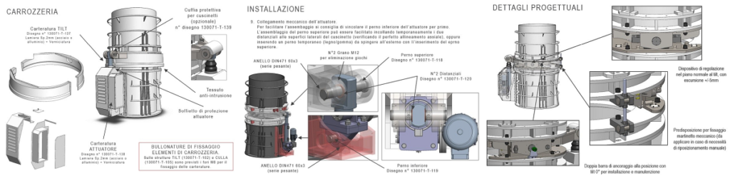
- Provision for Manual Locking Device at 0° Position
- Maximum Number of Actuator Operations per Hour: 5-20
- Materials for Non-Commercial Parts: Fe510 (S355JR), 39NiCrMo3 (pins and adjustable pin support), C40 (anti-tilt angle adjustment block)
- Actuator: Servomech BSA100 with ball screw featuring special 20mm diameter balls to ensure operation under strong winds (120 km/h) and survival in protection position with winds up to 200 km/h
- Bearings: SKF (GE series with D = 120mm and d = 80mm) with spherical joint
- Installation: Insertion of the tilt mechanism at 0° position and secured with safety pins
- Total Mass of Devices Mounted on the Trunk (turret, counterweights, reflector, accessories): 6520 kg
Altamax designed the tilt mechanism to be installed without interrupting or dismantling the antenna’s internal wiring. The project encompassed not only the design and structural calculation of the device but also the development of a detailed assembly and installation procedure.
All components of the tilt device, including mounting accessories, the connection structure with the electric actuator, and the lifting, adjustment, and safety devices, were simulated using Creo Simulate software (FEM method) to verify structural integrity and compliance with regulations. Additionally, dynamic responses to impulses caused by shocks or actuator actions (frequency response) were simulated using other software tools.
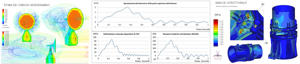
Some data (related to loads, stresses, and operating specifications) have been omitted for confidentiality reasons.